How conveyor trough angles affect skirt wear
 © Martin Engineering
 © Martin Engineering
 © Martin Engineering
 © Martin Engineering
 © Martin Engineering
 © Martin Engineering
 © Martin Engineering
Summary: Belt conveyor trough angles are based on precise decisions made according to several operational factors. Material size, the way it settles when loaded (angle of surcharge), and how it centers when the full trough angle is achieved are all factors that need to be considered both in the initial design and during retrofits.
The selection of the conveyor belt trough angle is also a compromise between the belt width, the skirtboard width, liner wear, throughput and the desired reduction in spillage. The balancing of these variables is important for reliable and safe operation over the long term. Failure to examine this issue may result in lower capacity, increased liner wear, excessive spillage and belt damage.
The CEMA geometry
In Chapter 4 of Belt Conveyors for Bulk Materials, 7th edition published by The Conveyor Equipment Manufacturers Association (CEMA), there are dimensionless ratios developed so that any 3 roll idler configuration can be evaluated [1]. The CEMA terminology is being used in this idealized analysis of the loading chute cross-section.
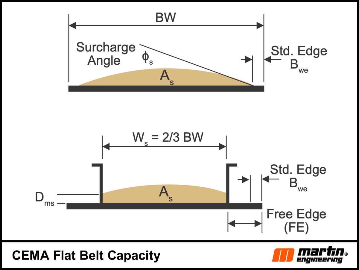
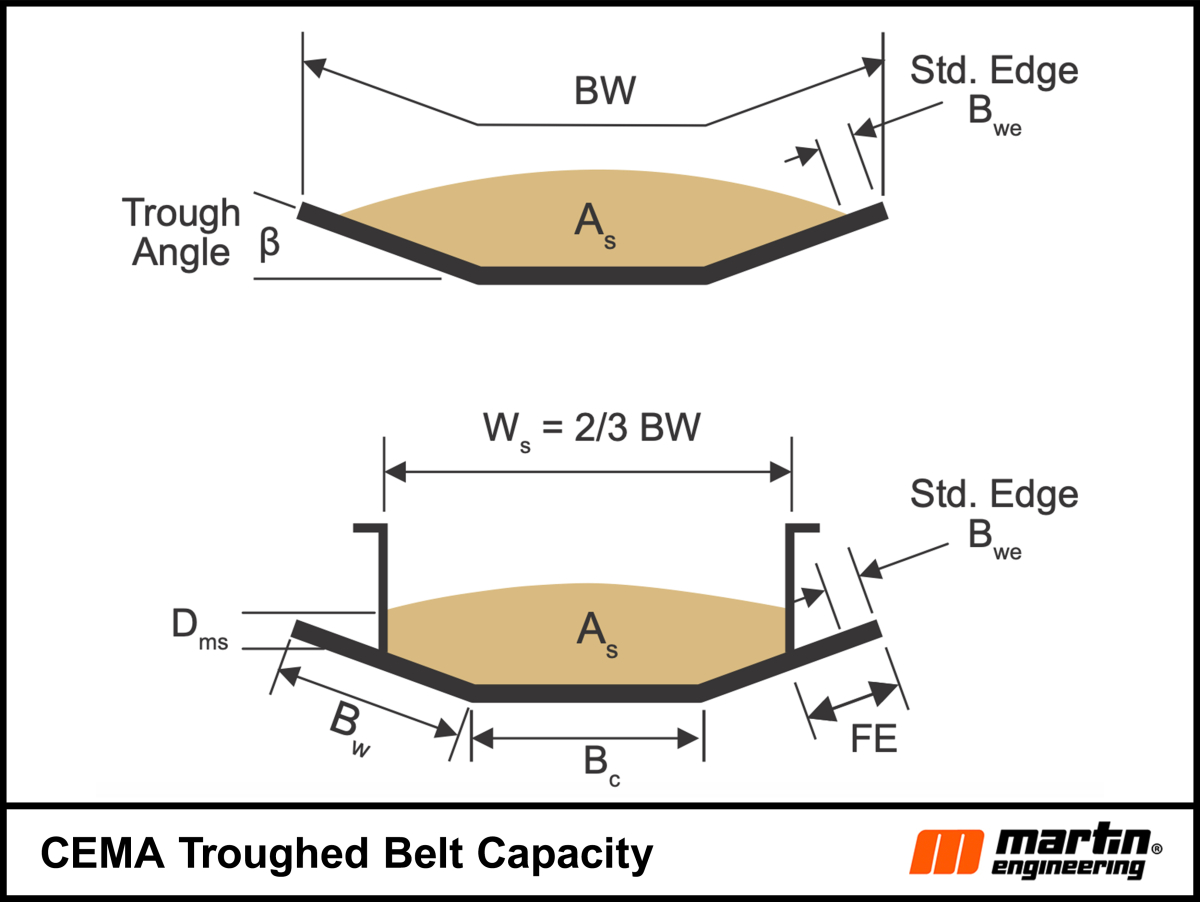
For simplification, the thickness of the belt and skirtboards are assumed to be zero, which is customary in bulk material conveyor belt engineering. The tolerances this introduces are minimal compared to the normal variations in the material’s bulk density and other factors such as loading and weather which affect throughput. Only one configuration of belt width geometry is studied but the method applies to any belt troughed by 3 roll idler sets. Similar ratios can be developed for non-standard idlers with more or less than 3 rolls. The detail of interest is the belt’s Free Edge (FE) that is available for the sealing system and belt mistracking (Fig. 1 and Fig. 2).
The theoretical CEMA cross-sectional area that a particular arrangement can convey is called the “CEMA Standard Area” (As). The area is developed using the standard edge distance and the bulk material surcharge angle. The top surface of the Standard Area is a circular arc tangent to the surcharge angle beginning at the Standard Edge Distance, Bwe.
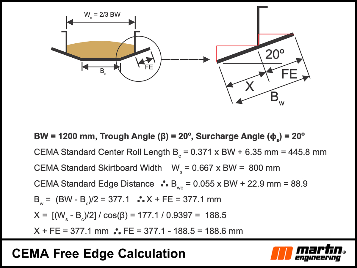
The standard edge distance is calculated through a formula and is intended to prevent material spillage from the belt as it sags between the widely spaced carrying idlers outside the load zone but not to determine the width of the skirtboards. The FE width of the skirtboards should be based first on reducing spillage by having adequate room for a side sealing system and secondly on how much bulk material is rubbing on the inside of the skirtboards or wear liners (Fig. 3).
While holding the skirtboard width ratio constant, the change in trough angle results in decreasing free belt edge as the trough angle increases, while the standard cross-sectional area, As, increases with a larger trough angle. The results for the four common trough angles are shown in Table 1. The CEMA mistracking allowance is based on the dimensions of the standard CEMA idlers and pulleys.
Table 1 shows how the trough angle affects the free edge and therefore the space for the sealing system. In addition, mistracking becomes problematic for 35° and 45° trough angles. A common low-cost OEM sealing system consists of an internal wear liner, a vertical external seal and angle iron clamps. The seal clamping arrangement needs to clamp close to the bottom of the skirtboards to reduce seal deflection. As the trough angle increases, the space available for the clamp decreases, raising the danger of the clamp rubbing on the belt and damaging it.
The external seal is typically a 13 mm thick rubber slab. A common problem with OEM sealing systems is the skirtboard and liner are often spaced well above the belt leaving the rubber seal to contain the material pressure. This means the cargo is continuously rubbing on the liners or exerting pressure on the seal. This prematurely erodes the rubber seal and wear liner resulting in leakage and belt damage. Material trapped in the space between the liner and the seal can cause belt grooving requiring more frequent cleaning and maintenance attention.
The capacity (cross-sectional area x belt speed x bulk density) rises by increasing the trough angle but often this is the only consideration when upgrading. Spreading the distance between the skirtboard walls reduces the available free edge and widening the belt increases the initial price. The solution is often to increase the belt speed while holding the tons-per-hour constant. This lowers the cross-sectional area needed to convey the same volume at the slower speed.
CEMA recommends reducing the standard cross-sectional, As, area by 15 % and provides recommended ranges of belt speeds for different materials and applications. The best approach is to base the belt width and speed on the life cycle cost and not on the price of installation. When increasing the cross-sectional area or belt speed, confirm that the existing belt, idlers and structure can handle the increased load. The design options of a new system dwindle as the price outweighs the cost.
By applying the traditional 2/3 belt width rule for the skirtboard widths and loading the conveyor at the CEMA 100 % full (As) cross-sectional area, designs can stay competitive and efficient. Not applying these principles results in material continuously rubbing on the internal structure walls, prematurely eroding them and causing more spillage. The height of material rubbing on the skirtboards or wear liners is called Dms in CEMA terminology. The theoretical Dms is 40 mm and for the 20° troughed belt and Dms is 73 mm for the flat belts used in this article.
While a little more spillage may seem to be a minor cost compared to the next wider belt, operators should consider the lifetime of additional cleanup and maintenance costs. Although there are other causes, spillage and wear are directly proportional to the square of the belt speed. There are also labor and replacement component costs, as well as indirect costs associated with more frequent cleaning and maintenance.
Recent projects applying the principle of long-term cost over initial installation price resulted in an increase of 25 % to belt life, 40 % to idler life, 60 % reduction in cleanup. Improving the access to transfer points made maintenance easier and faster which is widely acknowledged to drastically increase workplace safety.
Estimating cost savings for reduced safety incidents is one of probability and severity. Reducing the cleanup and maintenance limits the amount of contact workers have with the system, which lowers the risk of injuries. The severity of the accidents for cleaning and maintenance often centers around having adequate access. Conveyor transfers should not be placed against walls or made inaccessible by other structural elements and should be elevated for easy cleaning access.
Increasing production
Almost invariably the capacity is expected to increase to meet production demands over life of a conveyor system. If operators anticipate that production capacity may need to be increased, they should consider future production needs early and factor those into the original design. Rather than derating the conveyor capacity and speeding up the belt, another approach is to change the trough angle. Using the 1200 mm belt width example the capacity increases compared to a 20° trough angle are shown in Table 2.
Table 1 shows that the FE allowance for the sealing system is probably adequate at roughly 40 mm but if the trough angle is increased to 35° there is hardly any room for a sealing system. So, this is where the balancing act begins.
Common conveyor system adjustments for increased production include:
Narrowing the skirtboards to increase the height of the material rubbing on the liners
Different trough angles
Different belt widths
Increase/decrease belt speed
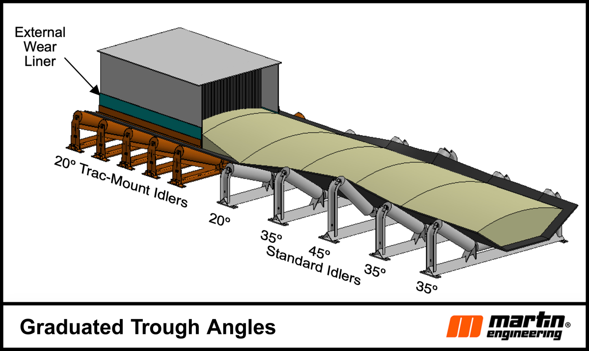
One technique that is used is 20° idlers in the load zone and then after the load zone transition to 35° idlers. The transition must be calculated using the same approach as the transition from the tail pulley to the troughing idlers. This design allows adequate room for belt wander and for a more robust sealing system. The 20° configuration gives more room for belt wander and the sealing system. The 35° idlers can carry more material. The height of the material rubbing on the skirtboards may cause wear issues. The same concept can be used to help center the load when off center loading causes mistracking in the carrying run.
In Fig. 4, the load cross-section is CEMA Standard or loaded from standard edge distance, Bwe, to standard edge distance based on a 35° trough angle. If there is not enough free edge with the selected idler for the expected belt wander and the sealing system thickness, consider lowering to 20° idlers under the skirtboards to increase the free edge. Then, when past the skirted area transition the belt into a steeper trough angle to help center the load and then transition back to 35° idlers for the carrying run. Another technique using varying trough angles is to help center the load which is also shown in Fig. 4 by transitioning into and out of a 45° idler. Note that this technique may cause shifting in material that can cause dust, so review options to mitigate or reduce emissions.
Because the loading was chosen as CEMA standard cross-section for a 35° idler, there is little room based on a 35-degree trough angle, (0.168 m2) vs a 20° idler standard cross-section, (0.128 m2). When the trough angle is lowered to 20° the larger contained material area (0.157 m2) rubs against the wear liners about 120 mm. Table 2 shows how close the material leaving the enclosure spreads out to the edges of the belt which further justifies looking at derating the capacity to accommodate surge loading and belt wander.
Service friendly
Making the replacement and adjustment of the seal and liner system easy is important for safety and controlling costs. Mounting the wear liner on the outside of the skirtboards and then placing the seal against the liner does several things. It eliminates the gap, which is the thickness of the skirtboard side wall, created by putting the liner on one side of the skirtboard and the seal on the other. This gap can catch and hold material and abrade the belt. Conventional systems weld wear liners onto the inside of the skirtboard making adjustments or replacements require hours of confined space entry involving two or more workers. Moreover, it makes the job more difficult, dangerous and time-consuming than necessary, raising the cost of operation.
Other idler configurations
The CEMA method using dimensionless ratios can be used to analyze any 3 roll idler sets either fixed or garland by substituting the actual dimensions in place of the CEMA standard assumptions. There are many other idler designs available today to address various needs but all can be studied using basic trigonometry. Typically, the center roll of a set is the most heavily loaded. To increase the load capacity the center roll is often made shorter than the wing rolls. Extending the life of heavily loaded idlers for faster belts can be achieved by widening the diameter of the center roll so it rotates slower. Custom and adjustable trough angles are also available which can be used to help center or recenter the load and help reduce belt mistracking.
Conclusion
The selection of the trough angle for a new design or retrofit requires a holistic view. When production exceeds the original design or there is a significant material change, operators must confirm the existing belt, idlers and structure can handle the increased load. What seems to be an adequate trough angle for the carrying run may create excessive wear in the loading zone resulting in more frequent spillage, increased clean up and more regular maintenance. Optimizing trough angles and skirtboard widths to allow a robust sealing system is critical to reducing belt wear and damage.
Even with a good design the components in the loading zone are going to require more frequent replacement than the carrying idlers because they support not only the load but also the impact from loading and the pressure of the material on the skirtboards. Making maintenance and cleaning easier and less frequent reduces worker exposure to safety risks, lowers costs and improves productivity. Having adequate free belt edge to accommodate the sealing system and belt wander along with the idler design to handle the load is the path to lower overall costs. Remember, slow and steady always wins the production race.
Literatur • Literature
[1] Belt Conveyors for Bulk Materials, 7th edition, Conveyor Manufacturers Association www.cemanet.org
[2] U.S. Occupational Safety and Health Administration (OSHA), “OSHA Safety Pay$ Estimator”, Dec. 2023. https://www.osha.gov/safetypays/estimator