Combined co-current drying and counter-current cooling in
a rotary drum
Summary: The combined rotary drum dryer & cooler developed by Allgaier Process Technology enables the cooling of previously dried solids down to particularly low temperatures close to the ambient or cooling air temperature. Two years of development were invested in the new technology based on the Mozer system. This enables high energy efficiency, for example, with heat recovery based on the separate recirculation of the exhaust air from the cooler and evaporative cooling. Thanks to the single-shell design, the system is maintenance-friendly at the same time. Special designs are suitable for combinations of counter-current treatment, heat treatment, calcining or reaction control with subsequent cooling in the same unit.
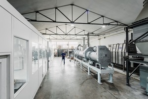
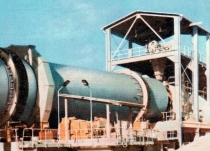
Allgaier rotary drum dryers/coolers have a worldwide reputation as high-grade, powerful and efficient drying and cooling systems (Fig. 1). They are used, in particular, for processing free-flowing bulk materials but also for sticky, lumpy or severely abrasive materials [1; 2]. The individual task-based design and manufacture of the rotary drums as well as special designs facilitate a wide range of applications for throughputs from 1 t/h to over 350 t/h, it being possible to integrate process steps combined with drying.
Many dryers and combined dryer/coolers of the Mozer system are used in the minerals industry, in the aggregates industry and in mining. Allgaier uses special solutions to cover not only convective methods but also technological processes for calcining as well as for indirect heating, drying and cooling extending to coating and granulation [5].
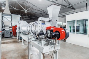
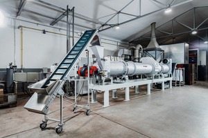
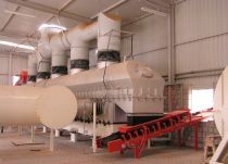
With the new TK-D rotary drum dryer/cooler (Fig. 2). Allgaier is presenting a further development of the previous, and already successful, TK and TK+ (TKplus) series of Allgaier dryer/coolers that can cool the product to about 50 to 60 °C [3]. With the development of the TK-D model, provision is made for the fact that in some application cases, e.g. foundry sands and in the product of ready-mix products, such as construction adhesives, and in the processing of materials for further treatment stages in recycling, increasingly low temperatures of the dried materials are required. These lie at around 30 to 45° C or close to the ambient temperature or that of the cooling air.
1 Design of a single-shell rotary drum
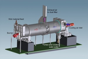
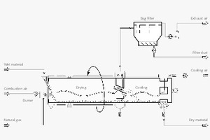
The dryer/cooler combinations known up to now have been designed as double-shell rotary drums in which drying takes place in the inner tube and cooling in the outer tube. However, in the new TK-D series, drying and cooling of the solid material is made possible in a single-shell construction of the rotary tube with separate areas for drying and cooling. This means that, in contrast to double-shell rotary dryer/coolers, inside the TK-D single-shell dryer/cooler type there are no areas of contact between the dry material in the cooling section with any hot outer surface of an inner drum in the inlet area of the dryer. Fig. 3 shows the basic operating principle of the new TK-D.
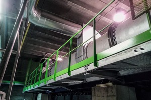
The new TK-D series has a specially designed central section that allows the exhaust air from the drying and from the cooling processes to pass through the rotary drum shell. At the same time, it ensures that the dried solid material is passed very rapidly from the drying zone to the cooling zone. Falling of dried material through the openings for the exhaust air is avoided by the special design of the central section. After the hot solid material has passed through the central area and into the cooling zone, it is cooled in counter-current and leaves the rotary drum through a solids outlet in a dry and cooled state (Fig. 4). The exhaust air from both the drying and the cooling is dedusted in a downstream bag filter and then discharged into the environment with the help of an extractor fan.
It is standard for warm, previously dried materials to be cooled with ambient air, temperatures up to around 10 K above ambient temperature being reached. With the use of optionally pre-cooled air, temperatures up to 10 K can be realized. The ambient air or conditioned cooling air is introduced via the casing through which the solids are also discharged. It is particularly advantageous that the length of the cooling zone can be designed for optimum cooling effect completely independently of the length of the drying zone.
2 Recirculation of exhaust air and heat recovery
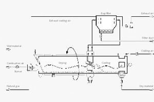
The central area of the TK-D, which may be divided into two parts by a dividing wall, has a configuration that allows to remove the two streams of exhaust air separately also. The moisture-laden dryer exhaust air is discharged into the atmosphere after it has been dedusted. But the dry, dedusted, exhaust air from the cooler can be recycled to the process as preheated drying air (Fig. 5).
The heat recovery achieved by recirculation of the exhaust air, which can be combined optionally with evaporative cooling to assist the cooling, leads to a further increase in the efficiency of the drying process and therefore to additional energy saving when compared with previous configurations. The evaporative cooling is achieved by secondary evaporation of some of
the residual moisture of the solids in the cooling zone.
3 Special processes
The separate introduction and removal of the air flows also permits different process control of the solids and the air. This means that either co-current or counter-current drying can be combined independently of one another with counter-current or co-current cooling.
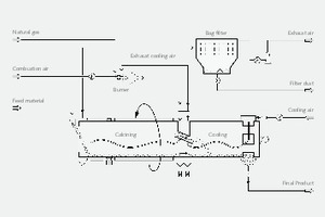
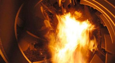
In particular, the possible counter-current routing of the hot gas and solids is suitable for various special types of high-temperature treatment, such as the calcining of solids followed immediately by cooling. The hot gas is directed into the connection in the casing in the central area that, in the standard design, is used for drawing off the drying air. The used hot gas is then drawn off next to the solids input. Here again the hot exhaust air from the cooler can be used, with or without dedusting, as preheated combustion air for the hot gas generator (Fig. 6). This achieves a significant saving in fuel.
4 Easy maintenance
The particularly abrasive action of minerals, such as quartz sands or slags, on equipment walls and, in particular, on the internal fittings in the dryer/cooler necessitates designs with ease of maintenance and repair for the processing of such products.
The TK-D rotary drum dryer/cooler is particularly maintenance-friendly because of its single-shell design. The rotary drums generally have a large diameter, so that it is easy to access the complete length of the drum for inspection or repair work. Inaccessible dryer areas as found in multi-shell drums do not exist in the TK-D.
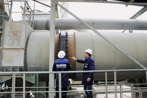
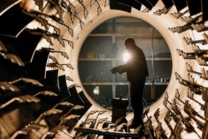
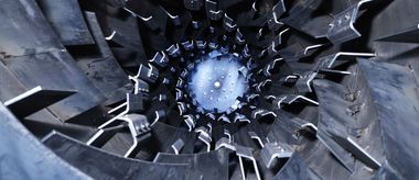
Generously dimensioned maintenance openings, also called manholes, are provided at safely accessible points on the TK-D rotary drum itself as well as on the dryer casing for inspection and maintenance. This means that worn internal fittings and any areas of the rotary drum that may have been affected locally by wear can be quickly discovered, repaired, replaced or optimized to increase production or in the context of a product change (Fig. 7). Allgaier offers the necessary service with globally operating staff and with appropriate supervision.
5 Experimental procedure and dryer design
The design of industrial drying plants usually requires trials on a pilot-plant scale. The parameters that are determined, such as residence times, temperatures, air and gas flows, achievable water evaporation rates and degree of drying of the end products, are then used for the individual plant design. This allows the manufacturer to offer comprehensive guarantees with respect to agreed plant performance, energy consumption and product properties.
Allgaier has a well-equipped test centre at its Uhingen site, with a large number of test plants for all the processes and machinery in the supply portfolio. Trials in laboratory plants that are too small can lead to uncertainties during scale-up so all the pilot plants are purposely designed on a semi-industrial scale (Fig. 8). This means that representative trials can be carried out under realistic conditions.
In the design of rotary drum dryers, the test results determined are combined with thermal balance calculations with the inclusion of a great deal of experience from similar plants that have already been supplied [4; 5]. It is becoming ever more important that a plant is designed as accurately as possible in order to conserve energy and resources and be competitive in the market.
First the important operating parameters, such as temperature of the air and solids, gas velocity and burner output as well as mass flows of the solids and hot gas temperature, are calculated using a thermal balance. It is then possible to determine the dryer volume and therefore the length and diameter of the rotary drum via the empirical parameter of the specific water evaporating capacity v [kg/(s m³)]. The specific water evaporating capacity v expresses the ability of a dryer configuration to evaporate a certain quantity of water per m³ of drum volume as a function of the chosen hot gas temperature. The parameter represents an empirical value that has been obtained from numerous plants supplied for the particular application and type of product. It is particularly dependent on the specific and optimum configuration of the internal dryer fittings but also on the product and on the material moisture level to be achieved [4].
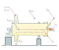
Fig. 9 shows the measurement points used in the test plant for the temperatures, air volume va,mix and burner output PB in a standard drying trial. The moist solid material enters the dryer with a mass flow m˙ Pr, temperature tPr,f and moisture content xPr,f. This solid material then comes into contact with the hot gases at a temperature te that are produced by mixing the burner gases with a proportion of ambient air. The burner output is determined with a gas flow meter. In addition to the hot gases and moist material the ambient air enters the dryer at a temperature tamb. This results in a total mass flow of the drying air m˙ L. The solid material is heated in the rotary drum to a temperature tP,tr and is dried to a residual moisture content xP,tr.
While the solid material is being dried, the drying air is cooled to a temperature ta,real and the moisture level in the air increases. There is some unavoidable leakage between the rotating drum and the discharge and exhaust air casing at the dryer outlet so a small false air flow from the environment with an ambient air temperature tamb becomes mixed in with the dryer exhaust air with a temperature ta,real. The resulting exhaust air flow is determined by measuring the exhaust air temperature ta,mix and the air velocity va,mix in the exhaust air duct.
All the parameters described are inserted in the balance equations (1), (2) and (3). Here Q˙ tot represents the total heat requirement that is needed for the drying process. The equations (1), (2) and (3) shown have been permissibly simplified in the balance: h1+x represents the enthalpy of the moist air, hPr is the enthalpy of the product, Q˙ r are the radiation losses and m˙ LL designates the false air flow. As a result it is possible to calculate the hot gas temperature te, which cannot be measured directly because of the sharp fluctuations in the mixing zone consisting of burner exhaust gas and incoming ambient air.
Q˙ tot = m˙ L [(h1+x)a – (h1+x)e] + m˙ Pr (hPr,a – hPr,e) + m˙ LLcP,L (ta,mix – tamb) + Q˙ r⇥(1)
Q˙ tot = m˙ LcP,L (te – ta,real)⇥(2)
PB = m˙ LcP,L (te – tamb)⇥(3)
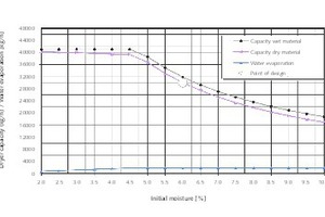
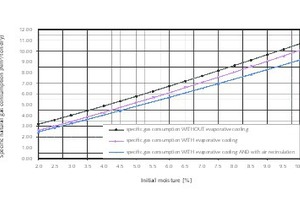
Fig. 10 and Fig. 11 illustrate the dependence of the solids capacity and water evaporating capacity (Fig. 10) and of the specific fuel requirement (Fig. 11) on the material inlet moisture content. This is based on the example of the drying and cooling of sands using a plant with a nominal dry material capacity of 30 t/h with an assumed solids input moisture content of 6 % at the point of design. The example assumes sands that only contain surface moisture.
Such a dryer is also capable of drying sands with higher initial moisture content, but the solids throughput (moist and dry = upper lines in Fig. 10) falls with increasing initial moisture content. With falling initial moisture content. the solids capacity (feed) can be increased to about 41 t/h. However, with a further reduction in initial moisture content to less than 4.5 % the solids capacity remains at the maximum value of the so-called mechanical limit because of the limited transport capacity of the rotary drum internal fittings that have been optimized for this case and the limitations of the dryer drive.
The lower line in Fig. 10 represents the water evaporating capacity which, because of the maximum installed burner capacity, remains constant above the nominal initial moisture content of the sand (point of design) but falls at low initial moisture contents and constant quantity of solids.
As a result, the specific gas consumption relative to the throughput of dry material rises with the initial moisture content of the sands being treated. The three virtually parallel lines of the specific gas consumption in Fig. 11 characterize the difference in energy requirement with and without evaporative cooling [3] through counter-current routing of the solids to be cooled and the cooling air in the cooling zone of a TK-D dryer/cooler (the upper two of the three lines in Fig. 11) or with evaporative cooling and additional recirculation of the hot exhaust air from the cooler (the lowest of the three lines in Fig. 11).
In the given example, the saving in fuel on account of evaporative cooling when compared with cooling without evaporative cooling lies in the range between 5 and 20 %, depending on the initial moisture content. Further savings of the order of about 5 to 10 %, depending on the initial moisture content, can be achieved with additional separate removal of the exhaust air and recirculation of the hot dry exhaust air from the cooler as preheated combustion and process air (Fig. 5). This means that, in total, there are possible fuel savings of around 16 % at the point of design.
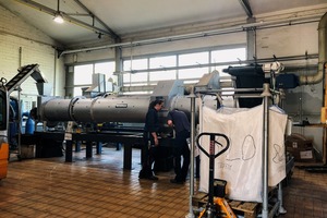
A new test plant (Fig. 2, 8, 12) was built parallel to the development phase of the TK-D rotary drum dryer/cooler. The total length of the rotary drum is 6.7 m with a diameter of 710 mm. The detailed configuration and arrangement of the internal fittings (“lifters”) that are important for efficient heat and mass transfer can be adjusted extremely flexibly in this test plant to suit the requirements of the particular process and the specific flow behaviour of the particular bulk material. The test plant was exhibited at the bauma, the world’s largest construction machine trade fair, in Munich in April 2019 and is now available to any interested parties for carrying out trials at the Allgaier test centre.
For the TK-D, the balance equations shown above were supplemented with the cooling air flow, which permitted analogous re-calculation and evaluation of the trials with the new TK-D system.
6 Practical applications
The new rotary drum dryer/cooler has already proved successful in various industrial applications. Its principle of operation is therefore reliably underpinned. Fig. 13 shows a TK-D with a total rotary drum length of 12 m and diameter of 1600 mm installed for a European customer. This is used for drying and cooling slag during metal recovery. The extraction casing in the central area is clearly visible.
For an initial moisture content of the slag granules of about 8 % (0 to 20 mm), the solids are dried at a throughput of 8 t/h to residual moistures < 1 % and then cooled to an output temperature of about 50 ºC. Water evaporating rates up to 800 kg/h are achieved. The product is therefore optimally suited for subsequent sorting process stages leading to final storage. One important reason for the customer’s decision in favour of the TK-D system was the good inspection and maintenance facilities of the rotary drum and the combination of drying and cooling in one unit.
In another application for a dry building materials plant in Latin America, natural sand with particle sizes of 0 to 3 mm and initial moisture levels of around 5 % is dried to residual moistures < 0.4 %. The subsequent cooling takes place to temperatures between 40 and 50 ºC, depending on the current ambient air temperature of between 20 and 35 ºC. As these low temperatures required by the customer for the dried material, even at high ambient temperatures, could not be achieved with multi-shell drying/cooling drums, these requirements were one of the main reasons for the customer’s decision to purchase a TK-D.
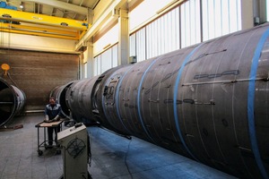
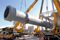
The dryer/cooler has a total length of 13 m with a rotary drum diameter of 2000 mm. Solid throughputs of up to 30 t/h are achieved. Fig. 14 shows the rotary drum during manufacture.
7 Final comments
The new TK-D rotary drum dryer/cooler provides the opportunity for efficient drying of free-flowing bulk materials followed immediately by efficient counter-current cooling. Drying and cooling take place in a single rotary drum, which provides very good access for inspection, maintenance and repairs. A specially designed central area for passing the dried solids into the cooling zone facilitates the efficient recirculation of the hot exhaust air from the cooler as preheated drying air as well as special designs for calcining or reaction control.
The recirculation of the exhaust air and optional evaporative cooling make the process energy-efficient. Reliable plant design is ensured by decades of experience from hundreds of references and the option of carrying out realistic trials in a flexibly configurable test plant.

